CFD Analysis of HVAC Duct
CFD Analysis of Supply AC Duct
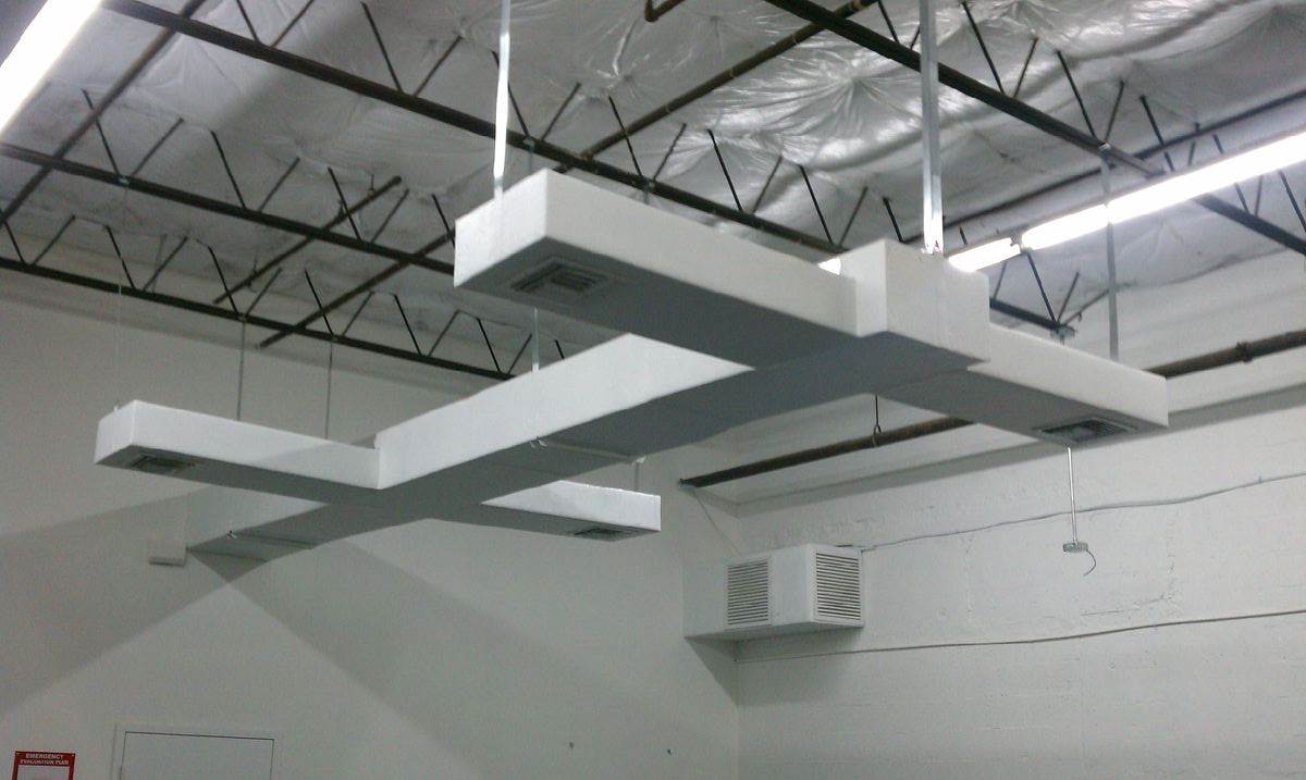
Supply air from AHU’s are carried to diffusers through ducts. The area of duct depends on volume flow rate. Starting from the AHU a cross-section reduction is preferred for the ducts, so that velocity will be maintained even at increased distance from the AHU. Besides flow rate, pressure drop is another parameter for duct design. Sharp bends in ducts results in higher pressure drop. Also the diffuser grill guides the flow out of the supply duct, so its shape can affect the distribution. In some critical applications where duct shapes can not be changed for aesthetics, guide vanes inside the duct can be used for flow regulations. Higher velocities inside ducts combined with sharp bends can result in flow separating from the duct walls. This can lead to noise generation due to turbulent eddies. Computational fluid dynamics will be helpful in determining the velocity and pressure drops inside an AC duct.
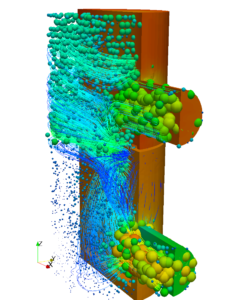
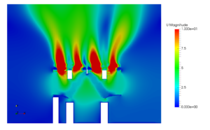
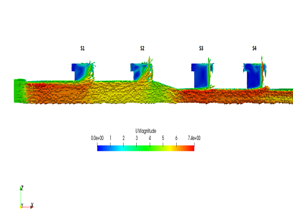
A supply duct inside a train coach is taken for case study. Two AC units are delivering air at two opposite ends of supply duct. In total 16 diffuser grills are present to distribute air in the coach. Train coach being symmetric, the axial half of the coach is considered for the CFD analysis. One of the post-processing image shows a velocity magnitude contour overlapped with vector directions. The branch duct portion containing diffusers are at 90 degree to the main duct. This is causing separation of flow from the duct wall. The flow separation has affected the volume flow rate through the diffusers though there is a reduction in cross-section area. This flow rate variation between diffuser grills are outside the acceptable variation of 10 percentage. A thorough investigation into the matter revealed, formation of vortices in poor flow diffusers. A second scenario, depicting worst case has also been tested where only a single ac unit is operational. Diffusers closer to the functional AC unit and the non functional AC unit have better flows. All the intermediate diffusers supply less air than average discharge rate. This has been also due to formation of strong vortex at exit of intermediate diffusers.
In order to avoid formation of vortex, flow guides have been introduced in the duct. Those flow guides divert required amount of flow towards the diffuser and rest going straight to other diffuser. The flow guides are able to break the vortices and a more uniform flow pattern is observed in modified duct. Some innovative modification in the duct geometry has made the flows in all diffusers nearly same while single unit is operational.


 Pressure vessels, pipes, expansion joints etc. are basic equipments for process industries. Pressure vessels are vessels working under internal, external or vacuum pressure, and possibly subjected to high temperature. Proper design and analysis is very important for the pressure vessels, as their failure can cause lot of hazards. Codes/ standards are used in the design phase, followed by analysis to ascertain stresses are within the allowable range. ASME provides wide range of guidelines for the proper design of such vessels.