CFD Analysis of Cyclone Separators
CFD Analysis of Cyclone Separators
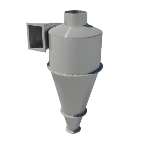 Cyclone separators are prevalent in process industries for separating oil droplets or dust particles from gases. These work on the principle that centrifugal force on a particle is proportional to its mass. So higher the mass, higher the centrifugal force. In cyclones, gas enters tangentially and produces a swirl motion. Due to the swirl higher mass particles stay towards periphery, strike on the wall and gets collected at a opening down below. A vortex that is generated inside cyclones drives the separation process. Better cyclone is the one with better overall separation efficiency. Along with separation process, there are associated losses in pressure energy at cyclone inlet, in the main body and in the vortex finder. CFD simulations can be used for deciding various design variables for cyclones.
CFD numerically solves mass, momentum and energy conservations. But turbulence adds extra complexities in the analysis. Let us look in the context of cyclones. Flow inside cyclones are highly turbulent and anisotropic. Hence isotropic turbulence models are not the best way to describe these flows. RNG and RSM turbulence models are most suited for swirl scenarios, where swirl number would decide whether to go for RNG or RSM. Highly swirling flows are solved in RSM due to its capabilities to resolve anisotropy in turbulence. In conjunction with turbulence, phases present in the fluid stream is also to be dealt during the analysis. The analyses would involve multiple phases, one continuous and some dispersed phases. Those analyses are done as Euler-Euler or Euler-Lagrangian analyses.
A case study show casing our capabilities on cyclone separator analyses is presented below.
The cyclone for the analysis is part of a petro-chemical separation process. In this study, gas is the fluid to be getting cleaned of oil, water droplets and dust particles.
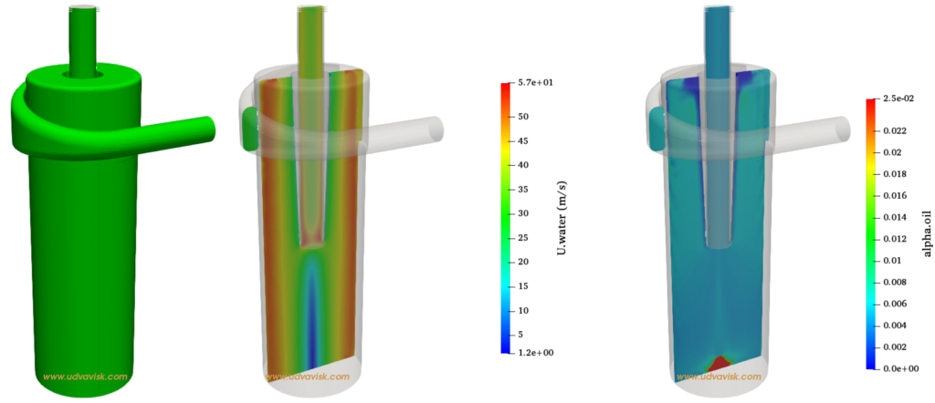
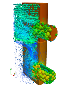
The left side image shows the fluid domain, middle image is velocity contour of water droplets and right image is the volume fraction of oil. The red region, corresponding to higher volume fraction of oil can be seen at the bottom of the separator. Except those contours, grade efficiency curves can be obtained by considering distribution functions for incoming particles. Pressure looses due to flow path can also be estimated from CFD studies. Turbulence generated in a Swirl fuel injectors in case of an IC engine can be analyzed in similar way as of cyclones. In some other devices, like an arterial line filter (used as a device to remove gases in blood flow) even isotropic turbulence assumptions provides accurate result, due to low swirling effect.


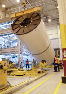
 Pressure vessels, pipes, expansion joints etc. are basic equipments for process industries. Pressure vessels are vessels working under internal, external or vacuum pressure, and possibly subjected to high temperature. Proper design and analysis is very important for the pressure vessels, as their failure can cause lot of hazards. Codes/ standards are used in the design phase, followed by analysis to ascertain stresses are within the allowable range. ASME provides wide range of guidelines for the proper design of such vessels.