CFD Analysis of Diesel Generator (DG) Housing
CFD Analysis of Engine Diesel Generators
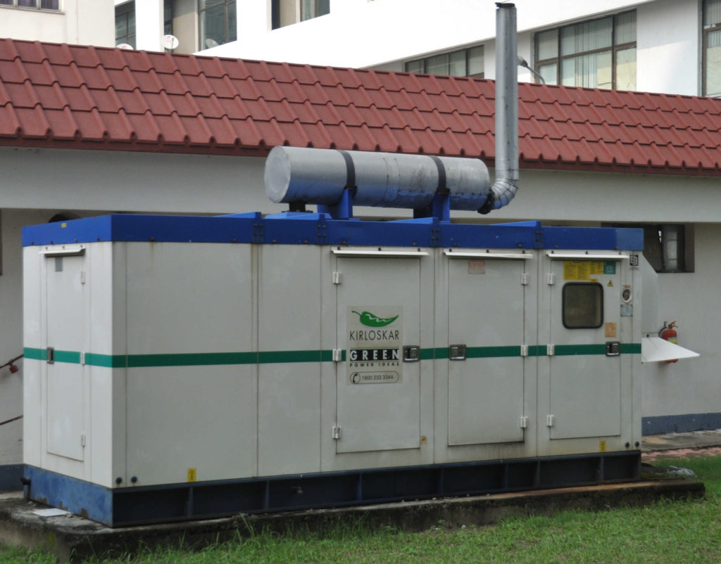
Diesel engines dissipate heat during electric energy generation and a sufficiently ventilated space is required to keep the temperature within threshold. Heat is removed from the generator set by inducing flow with fans. The fan flow is obstructed primarily due to diesel engine and generator. Some minor resistance to the flow is offered due to battery banks, fuel tanks, inlet and exhaust pipes from the engine. Weather louvers and noise dampers present near the hosing exhaust are also major obstruction to the flow. Along with inside housing flow, one more flow has to be taken care of is wind flow over the housing. This is because of the possibility of wind blowing over the housing which might re-circulate the exhaust gases towards the engine inlet.
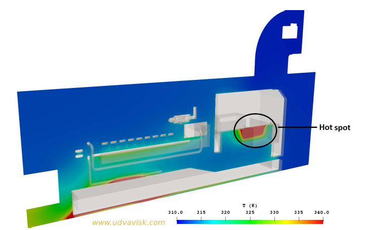
In a CFD analysis of diesel engine driven generator, flow both inside and outside of the housing can be taken care of. Both k-epsilon and k-omega turbulence models can be used and it is advisable to use finer cells near the wall to keep the wall y-plus values within limit of selected turbulence model. Temperature inside the housing would vary with maximum temperature near the engine. Some spaces near the engine where flow may not reach properly, the temperature may exceed the limit value. Such spaces should be identified and inlet air should be directed towards those hot spots with the help of flow guides.
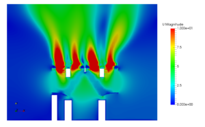
A CFD study showing such temperature hot spot is shown below. This can be reasoned out based on velocity contour. The velocity at this region is not sufficient, hence convective heat transfer is less and temperature is higher. The temperature contour can be obtained at various planes and it can be seen in conjuncture with velocity plot.
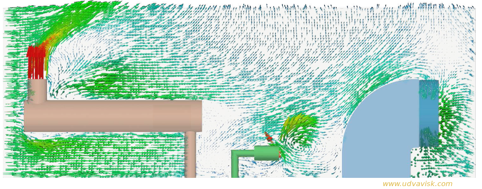
A CFD study pattern of air flow over the engine diesel generator housing is shown in image below. The wind is blowing from the left hand side of the image. Engine exhaust gas is carried away some distance towards right. In middle of the picture engine intake manifold. A small re-circulation zone is visible near the intake due to combined movement of wind and suction effect of fan. But there is no exhaust air near the engine intake. Those CFD studies would be immensely helpful in taking remedial actions before assembling such packages.


 Pressure vessels, pipes, expansion joints etc. are basic equipments for process industries. Pressure vessels are vessels working under internal, external or vacuum pressure, and possibly subjected to high temperature. Proper design and analysis is very important for the pressure vessels, as their failure can cause lot of hazards. Codes/ standards are used in the design phase, followed by analysis to ascertain stresses are within the allowable range. ASME provides wide range of guidelines for the proper design of such vessels.