CFD Analysis of Mixing Phenomenon in Flash Mixer, Coagulation and Flocculation Chambers
CFD Analysis of Mixing Phenomenon in Flash Mixer, Coagulation and Flocculation Chambers
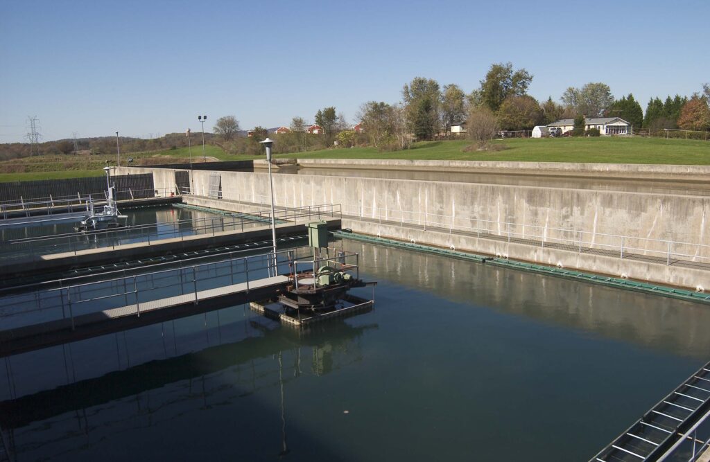
In Water treatment plants, the most commonly followed processes include screening, pumping, aeration, chemical injection, rapid mixing, coagulation-flocculation, filtration, and disinfection. Even after passing through the screening section, the raw water contains some tiny solid particles called colloids, which have passed due to their small size. These finer particles are removed by a series of processes called flash or rapid mixing, Coagulation, and Flocculation.
Flash Mixing and Coagulation
In the flash/rapid mixing process, chemical substances called coagulants are introduced into the flash mixer the mixture is agitated rapidly by the agitator blades. This ensures that the chemicals are mixed well with the water so that it neutralizes the finer particles, thus making them to attract each other (neutral charge attraction due to Van der Waal’s forces) forming large clumps. This process is termed as Coagulation.
The mixing efficiency of the flash mixer depends on the velocity gradient inside the tank. The velocity gradient (G) is influenced by factors such as mixing power applied to the water (P), dynamic viscosity of the fluid inside the chamber (μ), and volume of the mixing chamber/basin (V).
G = (P/μV)^0.5
Flocculation
After coagulation, clumps of minute particles (flocs) are moved to the flocculation chambers where the flocculants are added to the mixture. Flocculants are chemical substances that promote the agglomeration of fine particles present in a solution, creating a floc, which then floats to the surface (flotation) or settles to the bottom (sedimentation). These chambers are arranged in the order of decreasing mixing speeds. The flocs travel from one chamber to another chamber with size of the flocs increasing in the successive chambers as an effect of variation in mixing speed (high to low). The flocs are prevented from breaking due to the agitating action by allowing variable sizes of flocs to accommodate in chambers of different mixing speeds. The large flocs formed then finally settle down in the sedimentation chamber thus leaving the water with low turbidity.
Scope of CFD
With the help of Computational Fluid Dynamics (CFD) Simulation,
- Mixing intensity can be determined.
- Residence time inside the mixer can be determined.
- Turbulent kinetic energy inside the tank can be determined.
Performance of different agitator blade designscan be studied.
Velocity and mixing pattern inside the mixing chamber can be predicted.
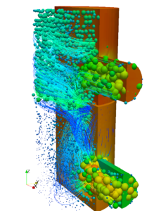
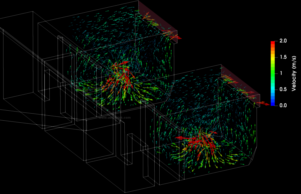
The following image represents the CFD analysis of Flash mixing, where the water enters two flash mixer chambers and are subject to mixing through vertical shaft agitators is shown below,
The velocity vector images represents the magnitude and direction of the flow at every point. The arrows are colored and size according to their velocity magnitude. For example, A red colour means velocity greater than or equal to 2 m/s.
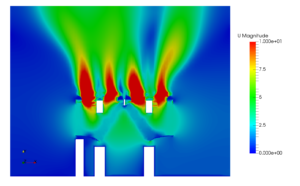
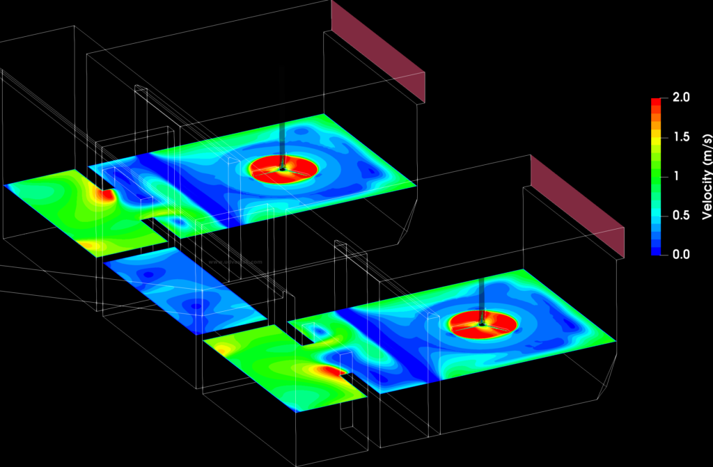
The velocity contour plot represents the mixing pattern inside the flash mixer chamber.


 Pressure vessels, pipes, expansion joints etc. are basic equipments for process industries. Pressure vessels are vessels working under internal, external or vacuum pressure, and possibly subjected to high temperature. Proper design and analysis is very important for the pressure vessels, as their failure can cause lot of hazards. Codes/ standards are used in the design phase, followed by analysis to ascertain stresses are within the allowable range. ASME provides wide range of guidelines for the proper design of such vessels.