CFD Analysis of Proton-Exchange Membrane Fuel Cell (PEMFC)
CFD Analysis of Proton-Exchange Membrane Fuel Cell (PEMFC)
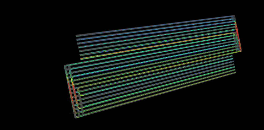
In PEMFC, the fuel being used is hydrogen and the oxidizing agent is oxygen. They are capable of producing electricity as long as the reaction takes place. The fuel cell consists of an anode (fuel side electrode), cathode (air side electrode), electrolyte and a catalyst (which induces the reaction). The fuel cells are classified based on the type of electrolyte and start up time taken such as proton exchange membrane fuel cells (PEMFC), alkaline fuel cells etc. In PEMFC, hydrogen fuel is fed into the anode side passage and oxygen/air is fed into the cathode side passage. The catalyst splits the hydrogen into positively charged ions and negatively charged electrons using oxidation reaction. The proton exchange membrane (an electrolyte located between cathode and anode) allows only positively charged ions to pass through the cathode. Some of the electrons and ions combine at the cathode producing carbon dioxide, water and a certain amount of heat. The fuel cell could be stacked either in a series or parallel manner to produce the desired amount of energy. The efficiency of PEMFC depends on,
- Water management (crucial part of the PEM cells since it directly affects power output)
- Temperature management (could cause destruction if thermal loading is high)
- Hydrogen consumption
Scope of CFD
As the efficiency of the PEMFC is affected by the parameters stated above, CFD analyses plays a major role in deciding the finest design. With the help of a Computational Fluid Dynamics (CFD) simulation,
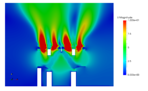
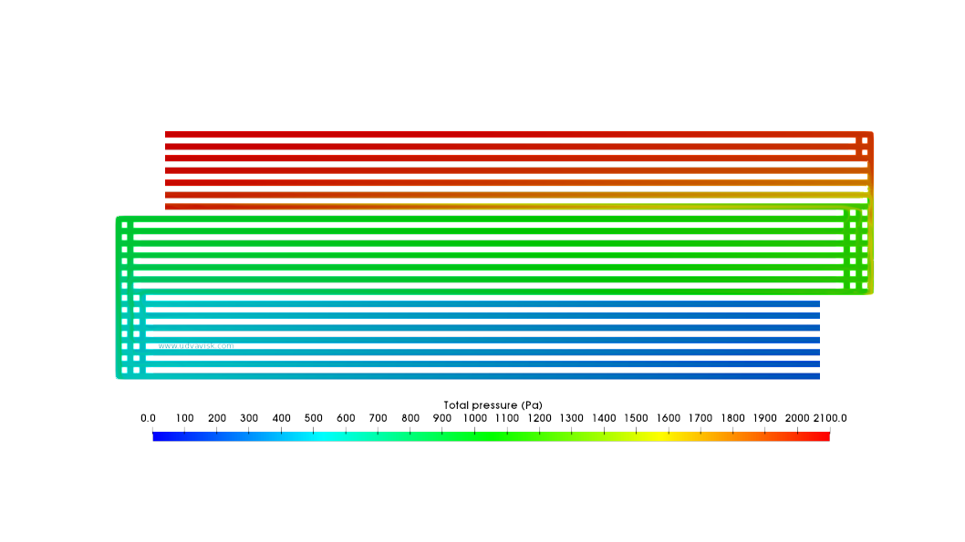
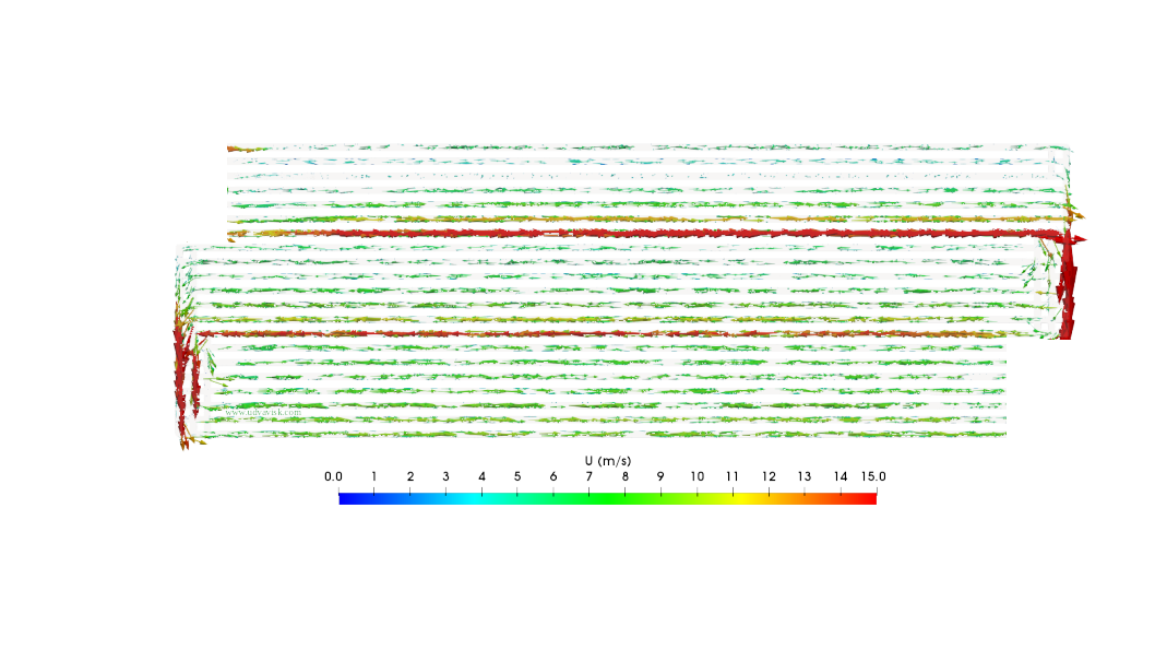
- The velocity distribution and pressure drop inside the fuel cells could be estimated at each point at any given time of the process.
- The temperature Distribution inside the fuel cell could be visualized.
- The areas of maximum temperature (hot spots) and vortex formation could be predicted.
- The effect on the fluid flow pattern and PEMFC efficiency due to the introduction of flow obstruction grids at various locations could be studied.
- The fluid flow behaviour for angled inlet and outlet channel conditions could be picturiesd .
- The output voltage for different inlet fluid flow rates could be analysed.
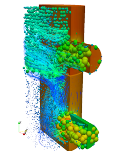
The following study illustrates the CFD analysis of air side electrode on a single channel of a PEMFC cell for a laminar flow,


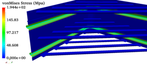
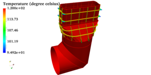
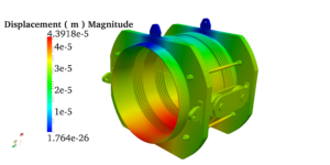
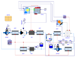
 Pressure vessels, pipes, expansion joints etc. are basic equipments for process industries. Pressure vessels are vessels working under internal, external or vacuum pressure, and possibly subjected to high temperature. Proper design and analysis is very important for the pressure vessels, as their failure can cause lot of hazards. Codes/ standards are used in the design phase, followed by analysis to ascertain stresses are within the allowable range. ASME provides wide range of guidelines for the proper design of such vessels.