CFD Analysis of Thermal Energy Storage (TES) Tank
CFD Analysis of Thermal Energy Storage (TES) Tank
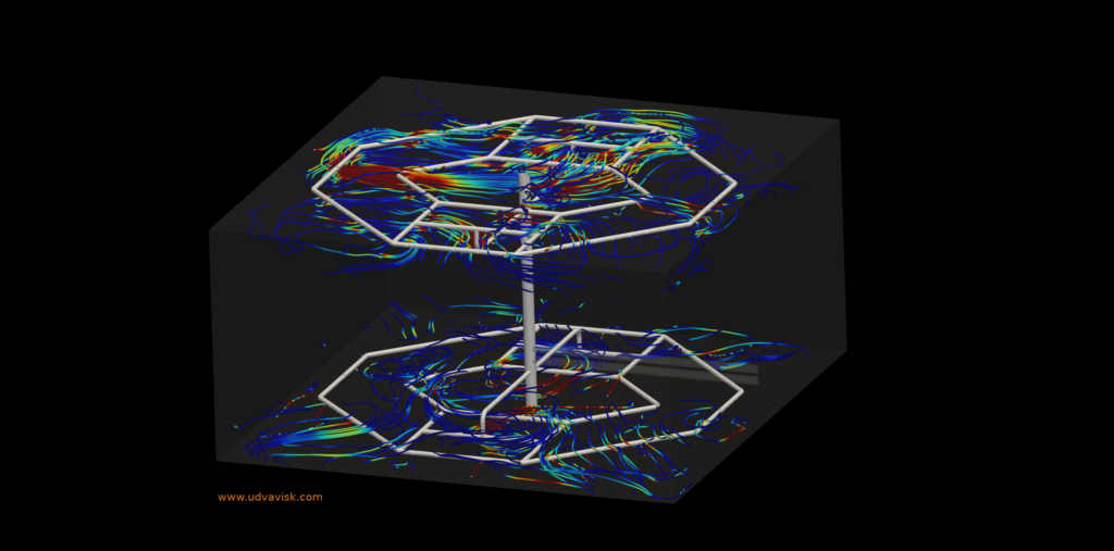
Thermal Energy Storage (TES) System is a widely proven technology for storing excessive thermal energy (hot/cold) during off-peak hours through cooling systems (chiller) and using that stored energy at peak load hours, thus minimizing consumption cost. The system stores thermal energy in the form of chilled water in case of Chilled Water Storage System. The other case, where ice is stored as thermal energy. The both cases require a Thermal Energy Storage vessel/device which is known as TES Tank. The Ice Bank Storage Tank is used for ice storage and Stratified Water Storage Tank is most commonly preferred for chilled water storage.
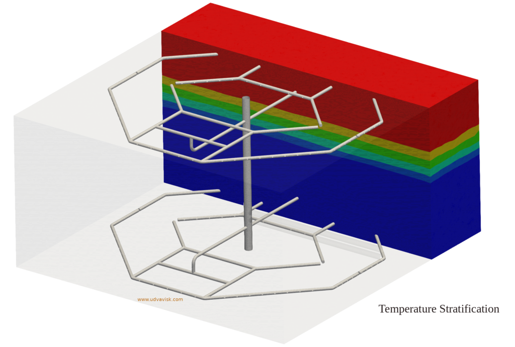
The Stratified Storage Tank operates by storing cold water and warm (return) water in a single tank.During charging, the chilled water is pumped to the bottom section of the tank through diffuser inlets, while an equal amount of warm water is being drawn out from the top section.During discharging, the chilled water is drawn out from the bottom, while an equal amount of warm water is being filled in the top. During charging and discharging operations, a natural phenomenon called Thermal Stratification occurs, that is the hot water (low density) remains at the top whereas, the cold water (high density) settles at the bottom of the tank. As a result, a transition region (Temperature Gradient) called thermocline is formed between the hot and cold regions having temperature ranging between the chilled water supply and the chilled water return. The Thermocline will gradually move from bottom to top while charging and from top to bottom while discharging. The thickness of the thermocline represents the inefficiency of the TES tank. The more efficient the TES tank the less thick the thermocline will be. The performance of TES tank solely depend on the thermal stratification which is influenced by these factors:
- Losing of temperature to the environment due to conduction. (Improper Insulation)
- Tank design. (Desired height and diameter – which allows for better stratification)
- Diffuser Inlet and Outlet design. (Which allows for laminar flow to prevent mixing of fluid regions thus promoting stratification)
Scope of CFD
With the help of a Computational Fluid Dynamics (CFD) simulation ,
- The temperature Distribution of the tank can be mapped.
- The thermocline thickness prediction, which can be optimized with test simulations.
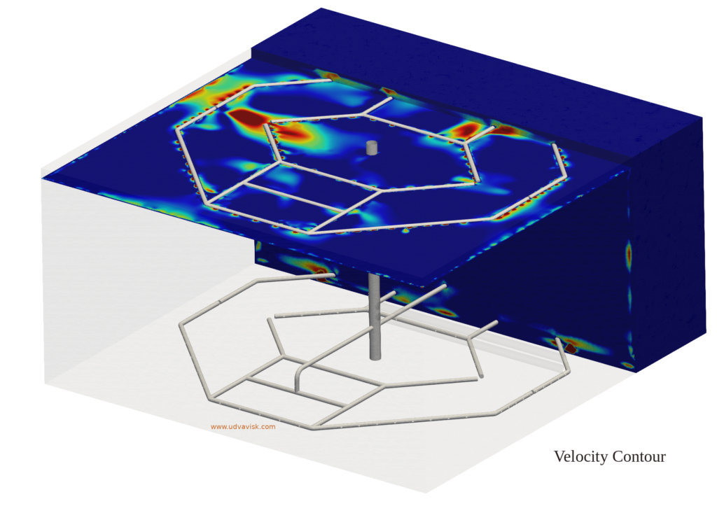
- Design, analysis and optimization of the diffusers.
- Fluid flow physics visualization throughout the TES tank.
- The Temperature, Velocity, and pressure at any point in the tank can be predicted at any given time of the process.
- Further observations and conclusions can be drawn from any given design condition.
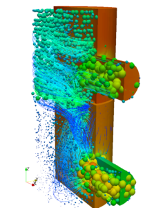
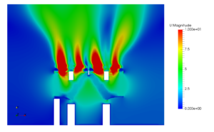
The charging and discharging in a TES tank is a transient state simulation. The following images represent the charging operation in a Stratified TES tank of 5 Lakh litre Capacity:


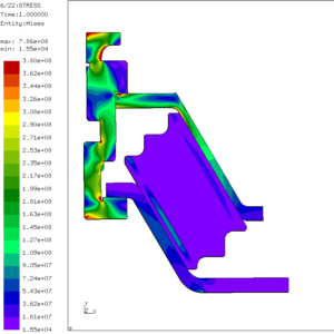
 Pressure vessels, pipes, expansion joints etc. are basic equipments for process industries. Pressure vessels are vessels working under internal, external or vacuum pressure, and possibly subjected to high temperature. Proper design and analysis is very important for the pressure vessels, as their failure can cause lot of hazards. Codes/ standards are used in the design phase, followed by analysis to ascertain stresses are within the allowable range. ASME provides wide range of guidelines for the proper design of such vessels.