CFD Analysis of Water Distribution Channels in Water Treatment Plants
CFD Analysis of Water Distribution Channels in Water Treatment Plants

Water Treatment Plants utilize a wide variety of processes and highly specialized setup/equipment to treat the water and its particles at different stages. The design and performance of these equipment are of prime importance for the process efficiency of the plant. The water treatment plant operates by conveying the water to various processes in a consecutive manner. The water advances from one process to another through distribution channels provided for each section. Uniform distribution of flow to each inlet in the distribution channel ensures an efficient process.
The treatment process gets affected if there is
-
Improper distribution of water to various openings/inlets in the distribution channel
-
Significant pressure drop in the pipe network
-
Insufficient flow velocity
-
Stagnation of flow/ re-circulation of flow
-
Erosion of equipment/pipe surfaces due to high velocity conditions
Scope of CFD
Computational Fluid Dynamics (CFD) simulations can be utilized for analyzing and predicting the flow dynamics throughout the water treatment plant even before the construction of the network. The findings from the CFD analysis guides in the decision making process in the design phase of the systems. From CFD simulations, the following can be studied:
-
Pressure drop analysis in the influent pipelines
-
Flow distribution analysis in an influent distribution channel to filters
-
Prediction of swirl inflow to intake pipes
-
Prediction of high erosion zones
-
Flow distribution analysis in a Grit chamber system
-
Improvisation of flow distribution in influent and effluent channels
-
Reduction of hydraulic loss at desired locations
-
Performance of hydraulic valves
-
Pressure surges in pipe network
-
Flow over weirs
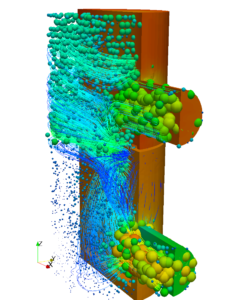
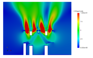
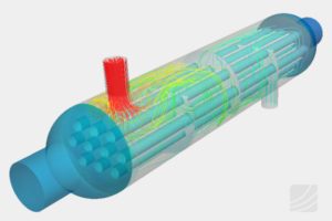
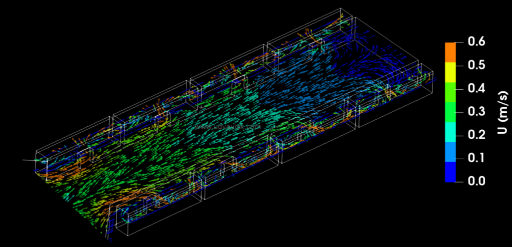
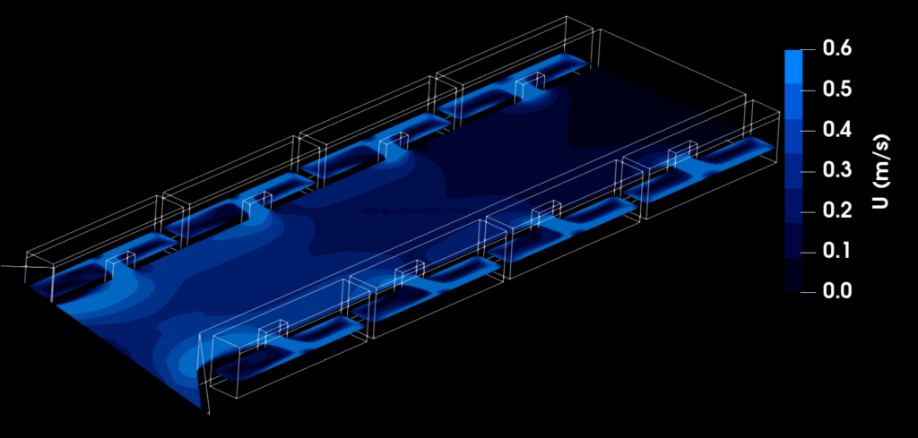
The following images showcase the CFD analysis of distibution channels in a water treatment plant
The velocity vector contour shows the magnitude and direction of the fluid flow inside the water distribution channel.
The velocity contour image represents the velocity distribution at each inlet of the water distribution channel.


 Pressure vessels, pipes, expansion joints etc. are basic equipments for process industries. Pressure vessels are vessels working under internal, external or vacuum pressure, and possibly subjected to high temperature. Proper design and analysis is very important for the pressure vessels, as their failure can cause lot of hazards. Codes/ standards are used in the design phase, followed by analysis to ascertain stresses are within the allowable range. ASME provides wide range of guidelines for the proper design of such vessels.