CFD analysis for a transformer room
CFD Analysis for A Transformer Room
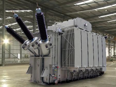
Electric substations use transformers to step up or step down voltage. In Gulf countries like Saudi Arabia, where dust storms are prominent, transformers are kept inside a room with perforated walls and roofs. The transformers generate a lot of heat due to various losses. For small transformers losses are less hence air circulation keeps the temperature within limits. Big transformers have special arrangements for cooling and should be placed in a well ventilated space to ensure temperature is within range. Fins take away heat from core and fans placed above transformers maintain good air movement through fins. This makes the transformers to be at intended temperature.The case study based on CFD analysis of transformer in an electrical substation in Dubai, UAE. The analysis was done as per the guidelines of Dubai Electricity & Water Authority (DEWA,Dubai, UAE)
The facility with perforated walls that houses bigger transformers is to be specially designed. The size of the perforation will affect the air movement inside a transformer room. So CFD results can be utilized to choose appropriate perforation sizes.
Closely spaced fins lead to a hotter temperature zone near the transformer. A forced convection is effect is created using fans to keep the fin temperature under control. The top panel temperature of a transformer can reach about 65 degree Celsius. In an enclosed transformer room, the fans blow air towards the roof. So roofs are with wire mesh to allow hot air to go out. To allow the fans to suck air at ambient conditions, perforation on walls do the job.
The CFD analysis of a transformer room is done with finer to coarser grid distribution, finer grids are placed near the transformer fins. The fans are treated as internal faces throwing air at pressure difference obtained from performance curve. The fins are treated as conductive walls with surface heat dissipation’s. Heat transfer over the fins occur primarily due to the movement of air caused by fan. So it is forced convection.
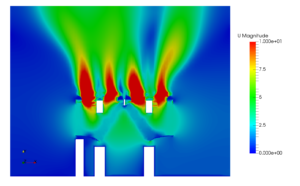
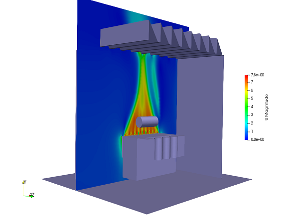
In this case study, a transformer room of 132/11 kV substation is considered. There are 4 different compartments housing transformers. Each transformers has a heat dissipation of 400 kW. The height of the compartment is about 10 meters and area is 70 m2. Due to geometrical similarities one of those compartments is considered for the CFD analysis. 28 fans are operating and circulating air around the transformer core. The post-processing picture represents a velocity contour in one of the planes at middle of fans. The throw from fans are clearly visible. The flow is gradually narrowing towards the roof of the room. This kind of pattern is due to formation of a vortex and inflow air from the porous wall side confine the fan flow. This flow is avoided by increasing the size of pores on the walls. Distribution of temperature over the transformer is observed to be acceptable. But some portion of the room is having higher temperature. Those are hot spots and additional fans are provided.

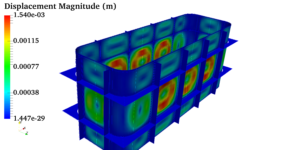 Pressure vessels, pipes, expansion joints etc. are basic equipments for process industries. Pressure vessels are vessels working under internal, external or vacuum pressure, and possibly subjected to high temperature. Proper design and analysis is very important for the pressure vessels, as their failure can cause lot of hazards. Codes/ standards are used in the design phase, followed by analysis to ascertain stresses are within the allowable range. ASME provides wide range of guidelines for the proper design of such vessels.