CFD in Air Cooled Condensers
CFD in Air Cooled Condensers
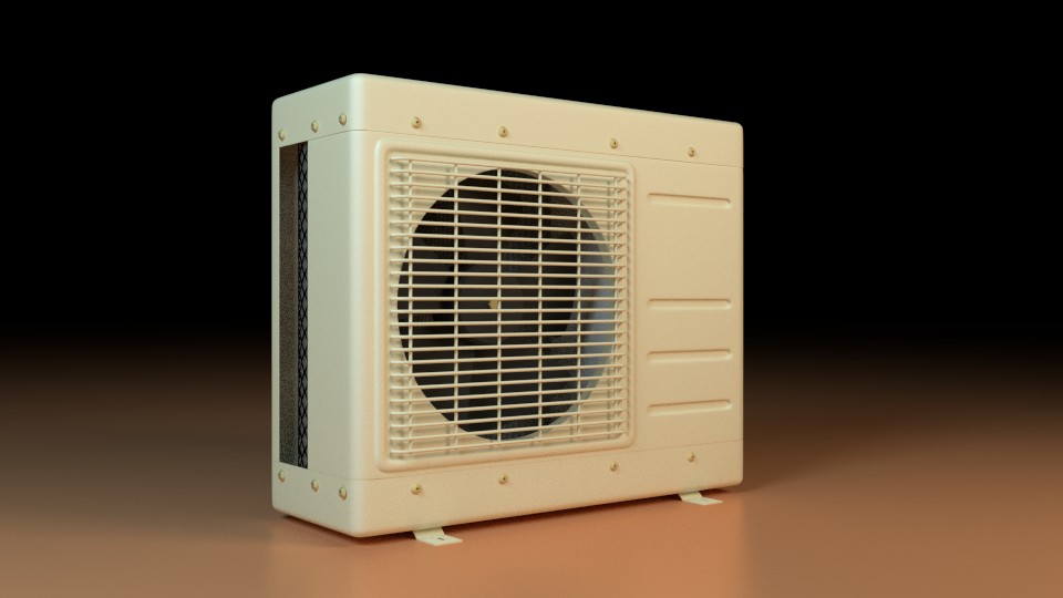
Air-conditioning systems work on principle of vapor compression cycle with refrigerant as the working fluid. Condensers are part of air-conditioning systems those facilitate heat rejection from hot refrigerant fluid to ambient. Few benefits of CFD will be discussed while describing key parameters affecting performance of air-cooled condensers of split ACs and central air conditioning.
The outdoor unit of split AC consists up of a finned heat exchanger (refrigerant being the fluid inside copper tubes), a fan sucking air over the finned heat exchanger, compressor and corresponding circuitry. Again the efficacy of the heat rejection process depends on how good the air flowing over the coils is carrying away the heat. This is a forced convection phenomena. Correspondingly the convective co-efficient is the quantity to be looked at. Higher convective co-efficient over the tubes and fins will guarantee an improved performance.
The optimization of outdoor unit of split AC would refer to maximizing the gains by higher heat transfer at condenser coils. This would require an optimized fan performance, which refers to increased velocity and flow uniformity over the condenser coil. Similarly heat transfer can increase with increased number of fins. But increasing number of fins per inch of copper tube will increase the pressure drop in the condenser unit and a higher capacity fan would be required. The trade-off between all the key input parameters can be seen by performing CFD analyses for various configurations. The fan performance can be checked in comparison to OEM provided data sheet and how well it is doing in out-door unit. Various parameters can affect the fan flow and the most important is relative position between venturi and fan. A similar study can be done for fins affecting flow of air. The fins in CFD can be considered as it is, but number of cells require to capture such small spacing would make the simulation a costly affair. Hence, the closely spaced fins are considered as porous domain. The porous domain is an equivalent space that would offer the same pressure drop as that of the fins. Darcy-Forchheimer is most common method for approximating the closely spaced fins to a porous domain.
Our CFD capabilities, in solving such problems are show cased in following images:
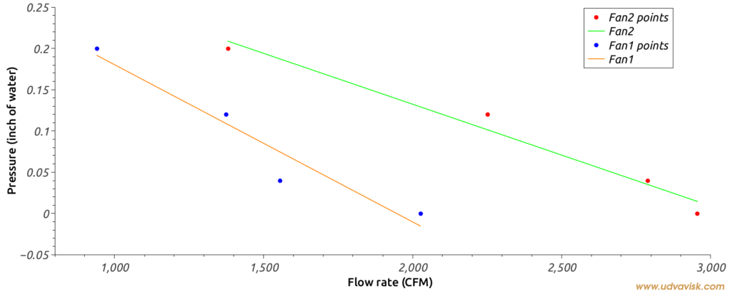
Comparison between performance of two fans :
Two different fans have been simulated as per manufacturer’s standard test conditions and the superiority of fan-2 over fan-1 is clear from the performance curve. The performance curve is a CFD generated curve, where fans are tested at various system resistance values.
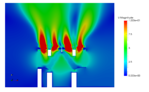
The better fan is chosen for further optimization of the condenser units. One of the images showing velocity variation over the porous condenser coil is shown in following figure.
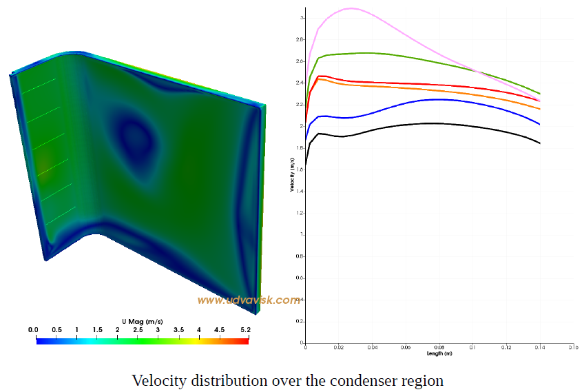
Those type of plots showing variation of velocity are called contour plots. Colors in contour plot corresponds to some values. In this particular contour plot blue corresponds to lower velocity regions and red to higher velocity regions
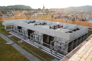
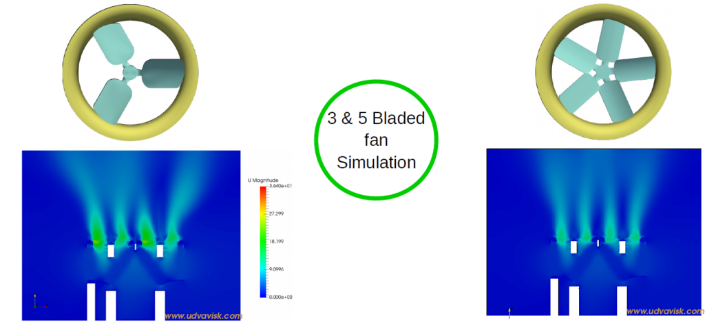
The same logic can be extended to an air-cooled chillers for central air-conditioning applications. Such condenser coils are big and arranged inclined/ vertical with fan placed over the coils. The coils will be placed in parallel to achieve targeted capacity. Fan and venturi studies are done to improve the performance of the unit. The flow over all the coils might not be same. The angle between the heat exchanger coils plays important role to make the flows uniform over the coils. The figure shows the throw of air from 2 chiller units with fans changed. Except the flow, the heat exchanger efficiency can be improved by considering fins with higher surface areas and low resistance to the flow. The CFD jargons that come into rescue in those kind of problems are MRF (Multiple reference frames), Porous Domain, convective and sometimes conjugate heat transfer.

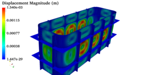 Pressure vessels, pipes, expansion joints etc. are basic equipments for process industries. Pressure vessels are vessels working under internal, external or vacuum pressure, and possibly subjected to high temperature. Proper design and analysis is very important for the pressure vessels, as their failure can cause lot of hazards. Codes/ standards are used in the design phase, followed by analysis to ascertain stresses are within the allowable range. ASME provides wide range of guidelines for the proper design of such vessels.