Energy efficient building design : energy modeling & analysis
Energy Efficient Building Design : Energy Modeling & Analysis
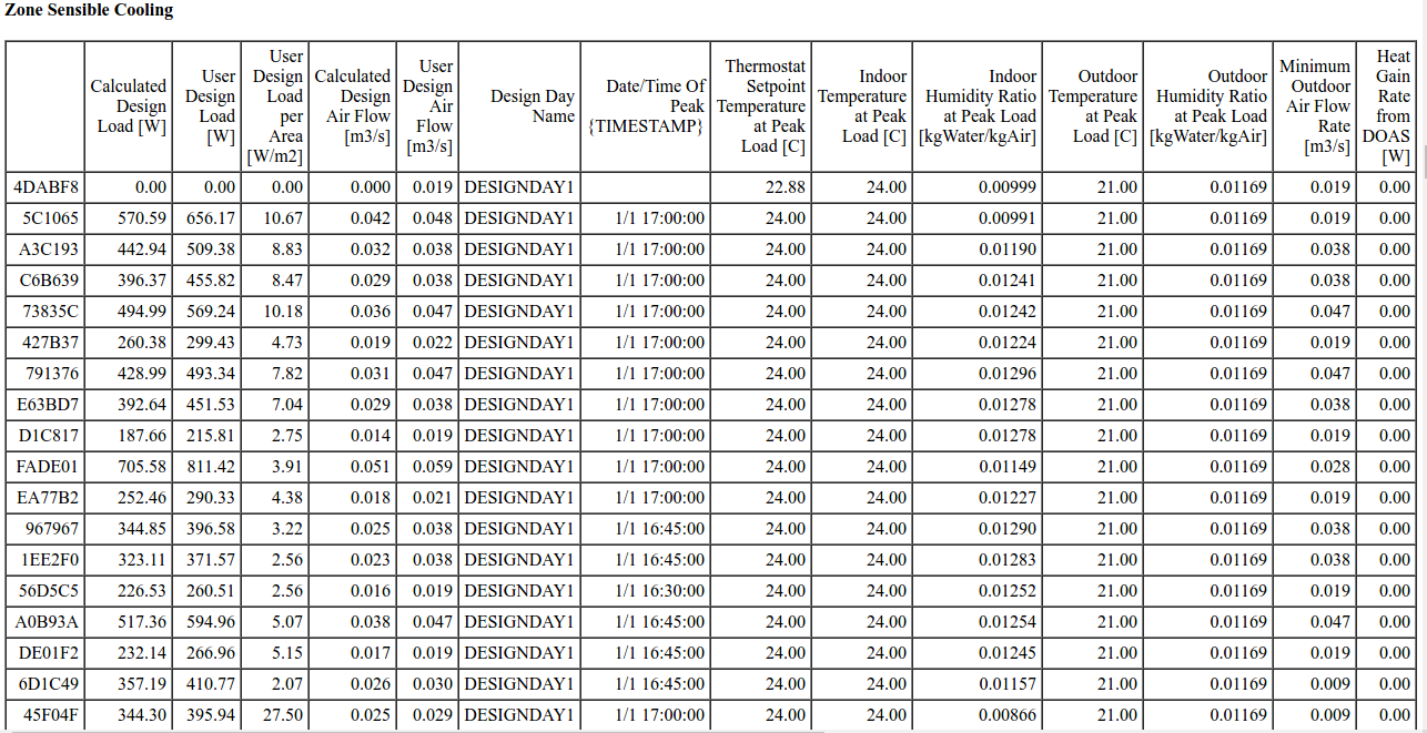
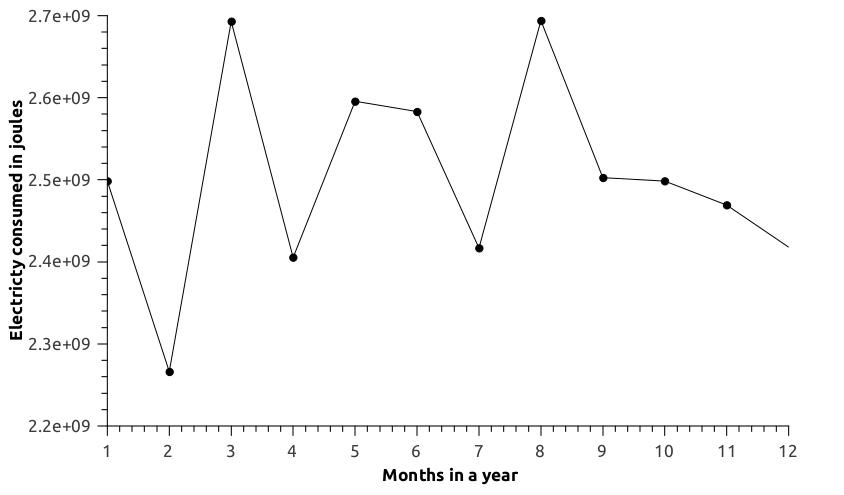
Chilled Water Coil:
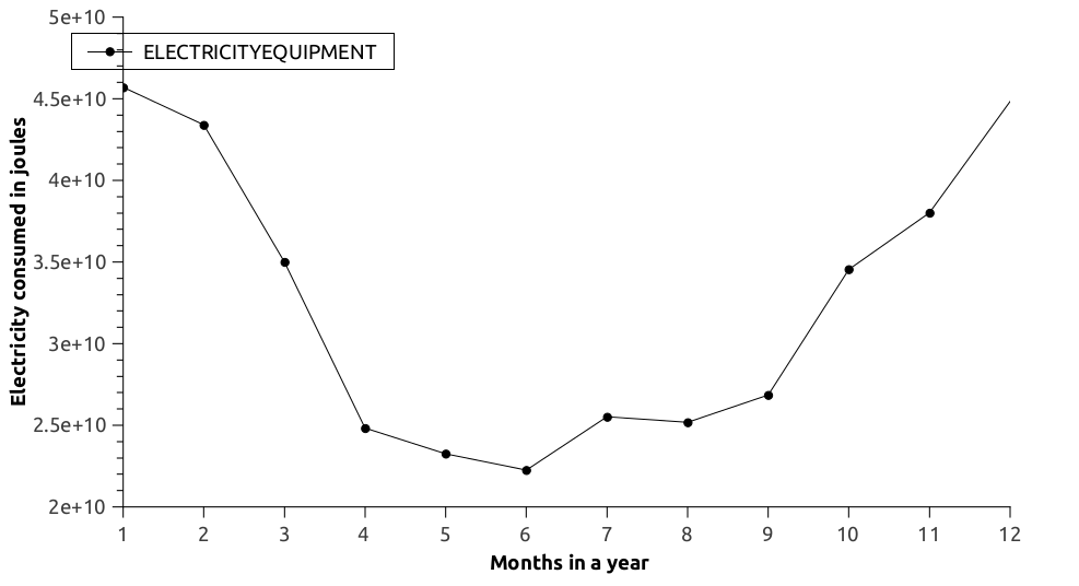
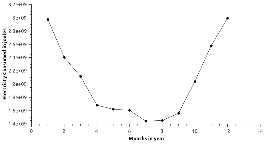
Fan Control:
Result and Conclusion:



Share this post: on Twitter on Facebook on Google+
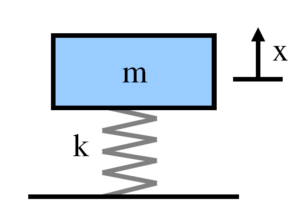
Springs helps in getting relatively large elastic deflection, and used in various industrial applications e.g. control of motion of machines, reduction of transmitted forces as a result of impact or shock loading, storage of energy, measurement of force etc.
It’s very important to design the compression springs with coaxial coils for appropriate stiffness. Many times the spring has to be designed as per the space available. For those scenarios Coil Thickness, Spring ID, Pitch and free length need to be found. The wire can be also be square, rectangular or virtually any shape, size or material. The helical compression springs need to be design and analyzed for compatibility with allowable stresses.
FE analysis need to be performed to determine the stresses and obtain the load vs displacement behavior. The spring behaviors could be non-linear due to large deformation. In those scenario the analysis need to be performed as non-linear.
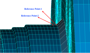
Many time, the residual life estimation need to be estimated for the welded joints with defects / imperfections. Weld defect can be due to misalignment, undercuts, solid inclusions, planar discontinuities etc. They need to be evaluated as per Welding Bulletin ( Recommendations for Fatigue Design of Welded Joints and Components by International Institute of Welding – IIW ), and appropriate method need to be used for the fatigue life estimation. Also, BS -7910 ( Guide to methods for assessing the acceptability of flaws in metallic structures ) can be used for the life cylce assessment.
There are several methods to estimate the residual life.
Nominal stress
The nominal stress which is the average stress across a section can be found out by FEA, without considering the weld geometry details. For simpler geometries, this can even be calculated from formula.
Hot Spot Stress
The structural hot spot stress can be determined either by measurement or by calculation. The procedure is first to establish the reference points and then to determine the structural hot spot stress by extrapolation to the weld toe from the stresses of those reference points. Depending on the method, there may be two or three reference points.In general, analysis of structural discontinuities and details to obtain the structural hot spot stress is not possible using analytical methods. Parametric formulae are rarely available. Thus, finite element analysis (FEA) is generally applied. The details for hot spot stress analysis is explained in the case study in section 6.
Extended Finite Element Method (X-FEM)
For the determination of stress distributions and stress intensity factors Extended Finite Element Method can be used. X-FEM is a numerical technique which extends the classical finite element method by discontinuous functions. This is one of the preferred techniques for solving crack propagation related problems. A key advantage of XFEM is that in such problems the finite element mesh does not need to be updated to track the crack path.
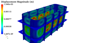 Pressure vessels, pipes, expansion joints etc. are basic equipments for process industries. Pressure vessels are vessels working under internal, external or vacuum pressure, and possibly subjected to high temperature. Proper design and analysis is very important for the pressure vessels, as their failure can cause lot of hazards. Codes/ standards are used in the design phase, followed by analysis to ascertain stresses are within the allowable range. ASME provides wide range of guidelines for the proper design of such vessels.
Similarly, the expansion joints are also very critical for the various operations. They are designed to absorb the movements due to thermal expansions, also any movements due to misalignment etc. Generally, EJMA (Expansion Joint Manufactures Associations) standard is used for the designing. For many non-standardize load cases, FE analysis is performed to determine the stresses more accurately.
The purpose of this process is to identify the main sources of vibration & acoustic noise, and work on the possible reduction in their levels. While under operation, there are many sources of mechanical vibration and associated noise, e.g. motor, bearings, cooling fans, housing etc. After the vibration analysis, the vibro-acoustic analysis for noise need to be performed, as many time the noises are structure borne.
Modal analysis: This analysis is required to find the natural frequencies and modes of vibrations. This will help in identifying the the possible resonance / vibration amplification effect due to proximity of natural frequency and excitation.
Frequency response and harmonic analysis: This forced vibration analysis is required to understand the load & displacement behavior while under operation. The analysis will provide us the forces that get transmitted to the structure. Accordingly will be useful in designing appropriate damper.
Vibro-acoustic analysis: This analysis is required to find out the acoustic noise level due to vibration. This will also help us in studying the interaction of acoustic noise with structures.
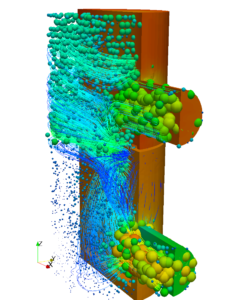
Strainer is used in many process industries for separating the solid particles from the fluids. Strainers are provided with cleanable screening elements, designed to remove and retain foreign particles. The objective of the client in this project was to find-out pressure drop across the strainer. As the perforated sheet and wire meshes are very small in thickness, they were modeled as porous elements.
The preliminary studies are done to find out the relation between velocity and pressure drop for the perforated sheet. Then the Darcy and Forcheimer flow coefficients are found out from the velocity and pressure relation. The CFD analysis was performed with appropriate inputs to understand the flow pattern and estimate the pressure drop.
Cases with different flow-rates and viscosities are simulated, also zone of high velocity gradient at the outlet were studied to understand high pressure drop. Finally, the report was prepared with the case results and documentations.
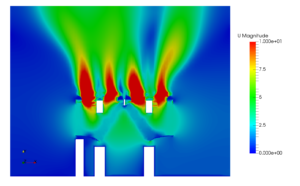
The condenser unit in the HVAC system is used to remove heat from hot fluid, then the fluid gets recirculated. In this project, the main objective of client was to improve the CFM of the fan by optimizing the shape of the unit. CFD analysis was performed separately for the fan to find out the maximum capacity under ideal condition. The cowl of the condenser unit was optimized based on different combinations of venturi shapes e.g. bell-mouth, inverted bell-mouth straight venturi etc . The effect of fan position with relative to the cowl was also studied
To make the analyses comprehensive the fin arrangements, V-angle of the heat exchanging plates was also studied. So effect of each parameter was simulated separately, and compared the results for the optimization. And also different fan configurations (number of fan blade parameter) are included in the analysis.
Finally based on the analysis, experiment was performed by the client with suggested changes, which lead to 21% improvement in CFM compared to the initial setup. The results with all necessary post-processing data were provided in an extensive report.
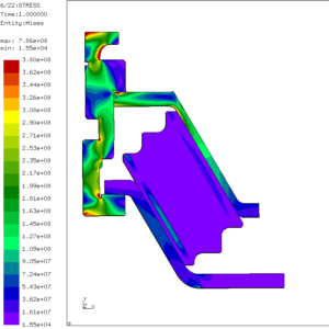
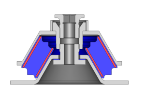
The wind dampers are mainly used for isolating the vibration from the wind turbine generator & gear-box. The non-linear analyses were performed for gearbox anti-vibration mount and Generator anti-vibration mount. Here the main challenging is to model the rubber as a hyper-elastic material.
Modal analysis and frequency response analysis were performed to understand the vibration characteristics of the dampers. The main objective of vibration analysis to avoid the resonance like phenomena. Fatigue life estimation was also performed for the components to ensure life corresponding to 20 years service period.
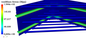
The analyses were performed as per the client’s requirement for the rectangular expansion joint. Static and buckling analysis of rectangular bellows expansion joint with the design pressure and design lateral+axial movement as per the operating condition were considered. The main objective of this project is thermo-mechanical analysis with contact. The clients are interested to see the maximum stress, displacement and temperature distribution of rectangular expansion joint. The movement in pipelines and ducting is occurred by the following,
As per the above mentioned thermal movements, the analyses are performed. Also, the stiffeners were to be analyzed and optimized. Finally, the reports with the temperature profile, stress & displacement was provided to the client.
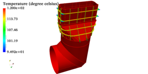
As the client was facing some repetitive issues with the installation, the objective of this project was to perform the failure analysis, and find-out the root cause of the problem. Also, to suggest appropriate corrective design changes were suggested based on the analysis. Thermostructural analysis, dynamic & buckling analysis were performed.
Based on the analysis, it was found that natural frequency of the bellow is coming in the close range of generator frequency; that was leading to failure of the welding joint between bellow and duct. The safe frequency for the bellow was suggested. Finally, modified bellows joint was used to perform the analysis.
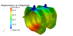
The scope of this project was to perform the mechanical integrity analysis (static analysis), low and high cycle fatigue and hot spot stress analysis of welding for the expansion joint. This expansion joints are used for pipe work and duct systems to prevent damage caused by thermal growth, vibration, pressure thrust and other mechanical forces. The causes of these stresses are internal or external pressure at working temperature, movement imposed on pipe sections by external restraints.
The clients was interest to find the fatigue life of the expansion joint. The FE-analysis was performed and compared with the EJMA standard. The main challenge of this project is to model and analyzing a welding. The welding s are modeled in required locations and perform the hot spot stress analysis by following the standard of International Institute of Welding (IIW) bulletin. Finally the results are submitted to the clients stresses at welding areas and the estimated life of the welding.
Buckling often refers to a large increase in displacement when there is a small increment in load. Buckling is one type of instability. Instability is a state in which small perturbations (e.g. small increments in load) can cause large changes in the response of the structure. Instability can be due to geometric effects (as is usually the case in buckling) or change in material properties. The buckling load factor (BLF) is an indicator of the factor of safety against buckling or the ratio of the buckling loads to the currently applied loads. Linear-buckling analysis ( eigenvalue-based buckling analysis or Euler buckling analysis) calculates buckling load magnitudes that cause buckling and associated buckling modes. FEA provide calculations of a large number of buckling modes and the associated buckling-load factors (BLF).
Nonlinear-buckling analysis requires that a load be applied gradually in multiple steps rather than in one step as in a linear analysis. Each load increment changes the structure’s shape, and this, in turn, changes the structure’s stiffness. Therefore, the structure stiffness must be updated at each increment. In this approach, which is called the load control method, load steps are defined either by the user or automatically so the difference in displacement between the two consecutive steps is not too large. Rotating machinery typically requires that designers consider the effect of pre-stress. Compressive stresses reduce natural frequencies. For example, an analysis of natural frequencies of a compressed column demonstrates that the first natural frequency declines with the load. Note that load magnitude corresponding to zero frequency equals the buckling load because this is when the compressed column looses its stiffness.
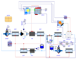
Building management system which is also known as building automation system is a computer controlled system that is employed in residential and commercial buildings to effectively control and monitor a buildings electrical and mechanical equipment such as ventilation, lighting, fire and power systems and more importantly security systems. A BAS typically consists of software and hardware that are integrated using internet protocols and open standards such as Device Net, BacNet, LonWorks etc. However, there is a great demand of energy for the proper functioning of all these components
The energy need of a building can be effectively determined using system modelling approach. Control strategies can be used to control and regulate parameters in a building. The parameters in subject are temperature, fan speed, pressure etc. The outputs can always be plotted as a function of time and other dependent variables. System modelling can be used to model a building in such a way that the comfort index of the occupants is optimized. They can also be used to study and simulate the functioning of every single system without much cost and more importantly the hardware needs for modelling a Building management system using system modelling approach is microscopic in nature compared to other graphically intensive packages.
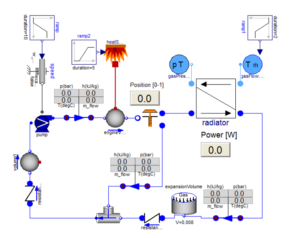
The greatest challenge faced by the designers of internal combustion engines is the implementation of a system for the purpose of removal of excess heat that is generated due to the combustion of the fuel. Mostly, in Internal combustion engines either air or liquid coolant is processed through a radiator cooled by air. For smaller engines the air cooled loops are light weight and relatively simple. However, there are complex engines where liquid cooled systems are used, which are quite intricate compared to its counterpart. The tricky situation is that the entire engine will fail upon the overheating of a single part. So, an ideal cooling system ensures that the temperatures are kept at a suitably low temperature.
Using the System modelling libraries it is absolutely possible to simulate the entire cooling circuit of an engine to study its performance so designers can effectively implement their design and it is also possible to obtain several plots such as fluid properties versus temperature, pressure. Every single component such as a radiator, thermostat, expansion tank, piston can be included and simulated in the circuit. The modelling software’s provide results in a more rapid manner compared to the commercial CFD packages floating on the market.
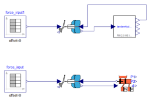
Actuators are basically used in all types of machinery. Pneumatic actuators use utilizes the energy of air pressure from the reservoir that is fed into a compressor to convert it into mechanical energy. A pneumatic actuator can execute several types of motion such as rotatory or linear depending upon the type of actuator used. Usually a Pneumatic actuator employs a diaphragm to move a valve stem or a valve control element.The pressure range within which the actuators work is too large that it could crush solid objects easily. So, precise measurements and analysis have to be conducted to ensure the smooth working of the circuit.
In system modelling approach, the user can model the circuit using blocks to control the opening and closing of flow paths. Moreover, the interaction between the flow network and the mechanical transnational work can be modeled. The results depicting the mass flow rates, pressures and temperatures within the actuators can be obtained for the purpose of analysis.
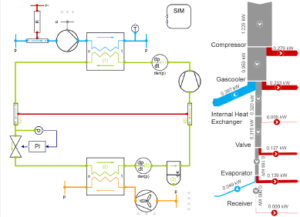
A typical HVAC system consists of several components working synchronously. The under performance of one component can deter the efficiency of other components thus utterly ruining the comfort level of the occupants in a zone for which the HVAC system is installed. Great precaution must be ensured while modelling a HVAC system in such a way that the individual components can handle the loads entrusted on upon them without breaking a sweat. Moreover, there are issues faced when modelling a HVAC system can solved only with adequate knowledge and resources.
System modelling of a HVAC system implies to the planning, design implementation, studying the input data and the conceptual modelling of the zones, outdoor and indoor air handling units. Unit the birth of computers, simple analytical methods were employed to determine the cooling and heating loads. Over the years due to the advent of computer capabilities several modelling techniques such as mathematical modelling, black box and gray box modelling have been developed to simplify the complexities in studying and implementing a HVAC system.
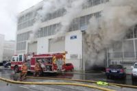
The warehouse are generally the storage building for goods, depending on the type of storage the fire analysis for the warehouse varies if chemicals are stored in the warehouse then the fire and smoke simulation should be accurate because the spread of fire is uncontrollable. Usually sprinkler are used to control the fire.
By doing Smoke and Fire Simulation for warehouse we can determine the effective response time of the sprinkler to control the fire propagation in the warehouse and also the amount of mass that can be consumed while burning of the material in the warehouse and the the heat flux which in the ware house can also be found using the smoke analysis.

Tall buildings have two principle components egress strategy and building performance.Building performance can be broken down into structural performance and fire spread mitigation.The evacuation strategy is concerned with the time required to safely evacuate the people.Time associated to evacuate people are of the order of minutes whereas the structural performance are of the order of hours,as the height of the building increases the vertical escape routes are limited.
By doing Smoke and Fire Simulation we can determined the evacuation time that is needed to safely evacuate the people from the building and also,control the smoke and fire by understanding the smoke propagation under the fire scenario. The visibility range in the building also be checked for the entire space during the fire and smoke propagation scenario.

The commercial buildings posses a greater challenge in the analysis, because of the number of parameter which are to be considered while analyzing, In commercial spaces mostly sprinklers are used to control of fire. Therefore the sprinkler activation time and the volume of water to be sprayed must be determined.
By doing Smoke and Fire Simulation the sprinkler location can be determined for the effective control of smoke and fire by understanding its velocity profile as well as the temperature profile under the fire scenario. In case of fire the smoke propagation can be predicted for the given space,the visibility range can also be checked for the entire space during the fire and smoke propagation scenario.

There are two types of parking space, open parking space and underground parking space.The problem that are usually faced in the underground parking space are high level of CO concentration ad carbon dioxide concentration under normal condition, In case of a fire the visibility and smoke density are the problem which are faced during evacuation.
By doing Smoke and Fire Simulation the jet fan location can be optimized for the effective removal of smoke by understanding its velocity profile under the fire scenario as well as under normal condition to remove carbon monoxide.In case of fire the smoke propagation can be predicted for the given space, the temperature and visibility range contour can also be checked for the entire space during the fire scenario.
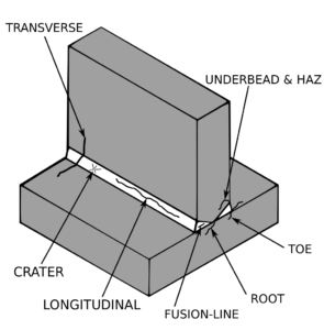
We provide service of components to determine whether equipment with existing flaws (such as distortions or cracks) found by inspection is suitable for continued service. The presence of a crack can significantly reduce the life of a component or structure. Codes and standards for pressurized equipment provide rules for the design, fabrication, inspection, and testing of new pressure vessels, piping systems, and storage tanks include:
However, some of these Codes do not address the fact that such equipment may degrade while in service, and that deficiencies due to degradation, or original fabrication defects may be found during subsequent inspections of in-service components. Use of fracture mechanics in fatigue crack growth and damage tolerant design requires knowledge of “pre-existing” cracks, either assumed or found using nondestructive flaw detection techniques .Fracture mechanics has been used heavily in the aerospace, nuclear, and ship industries with a recent extension to the ground vehicle industry. Our assessments include:
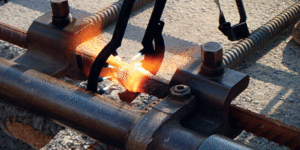
A welded fastening creates a strong and effective joint between two materials but it is also important to analyze the characteristics of the weld itself. During the welding process a local area is heated up rapidly with high thermal gradients as a consequence. The material expands as a result of being heated but the expansion is restrained by the surrounding colder, and stronger, bulk. This will give rise to the thermal stresses. The deformations due to welding are driven by the thermal expansion (temporarily) and the residual stresses (permanently). Stress and deformation are largely opposed. A high degree of geometrical restraint in welding results in high stresses and small deformations while an unrestrained weld produces lower stresses but larger deformations.
In our real problem we are dealing with a big calandria vessel, which houses the horizontal fuel channels, boilers, welded towers, windmill, and pressurized expansion joints. The stress coming from the welded models is really useful to find the fatigue life of the components. The international institute of welding recommends fatigue life of welded joints and components.
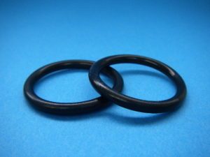
Elastomers are used extensively in many industries because of their wide availability and low cost. They are also used because of their excellent damping and energy absorption characteristics, flexibility, resiliency, long service life, ability to seal against moisture, heat, and pressure, non-toxic properties, moldability, and variable stiffness. Rubber is a very unique material. During processing and shaping, it behaves mostly like a highly viscous fluid. After its polymer chains have been cross linked by vulcanization (or by curing), rubber can undergo large reversible elastic deformations. Unless damage occurs, it will return to its original shape after removal of the load. Proper analysis of rubber components requires special material modeling and nonlinear finite element analysis tools that are quite different than those used for metallic parts. The unique properties of rubber are such that:
Any material behavior must be determined experimentally, and the wide variety of rubber compounds make this experimental determination even more important. The most important concept to recognize about rubber is that its deformation is not directly proportional to the applied load,in other words, it exhibits a ‘nonlinear’ behavior. In most of the time nonlinear elastic or hyper elastic Mooney-Rivlin or Ogden formulations (for rubber components) are widely used for the analysis. Most elastomers (solid, rubber like materials) have very little compressibility compared to their shear flexibility. In cases where the material is highly confined (such as an O-ring used as a seal), the compressibility must be modelled correctly to obtain accurate results. We are performed more case of stress analysis of rubber mount in windmill.
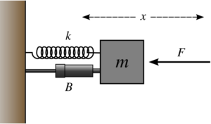
Vibration analysis is performed not only to do determine the design life of structures, but also determine how a component may have failed. When a physical system vibrates,it does so at particular natural frequencies and resulting mode shapes can be determined using modal analysis. For a simple structures like beams,bridges,etc,directly perform the modal analysis,while for more complex systems finite element analysis is performed to determine the dynamic response. The purpose of a modal analysis is to find the shapes and frequencies at which the structure will amplify the effect of a load. Free vibration is the natural response of the structure to some impact or displacement and Forced vibration is the response of a structure to a repetitive function that causes the structure to vibrate at the frequencies of the excitation. When you do modal analysis, you are asking, what are the dangerous natural frequencies that make you resonate? When you do frequency response, you are actually testing:Let’s input a load which will vibrate in a certain defined range of frequencies and let’s see how you actually deform.
Cause and effects of mechanical vibration
Almost all machine vibration is due to one or more of these causes : (a) Repeating forces (b) Looseness of the assembled components and (c) Resonance. Some of the industrial causes are Structural imperfection,Unbalanced shafts,imperfect geometry of gears,motors and generators,non-coaxial coupling shafts,wears off bearing,cams and couplings.
We have performed vibration analyses on valves, medical equipment, electronic components, pumps, structural support systems, windmill, generator mounts, gearbox mounts, anti-vibration mounts, bellow expansion joints,among other components. Vibration analysis is useful for all type of rotating components. Vibration analysis is uses for plant-based mechanical defect detection in order to reduce maintenance costs and equipment downtime. It can preemptively identify specific faults in rotating equipment, identifying the root cause of the problem and allowing you to do relevant maintenance.
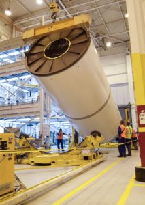
Finite Element analysis is a method that helps to simulate mechanical parts and systems to get information about failure, deformation an stresses under some various kinds of loading. Static analysis of an intelligent structure, for a example a structure integrated with distributed actuators and sensors, is presented by the finite element method. There are two condition for static analysis (1) No variation of force with respect to time, (2) All the forces and moments equal to zero in all directions. As structural collapse does not generally coincide with the appearance of the first crack or localized early crushing, it seems that the elasticity theory is a step back with respect to limit analysis.
The relationship between loads and induced responses is linear. For example, if you double the loads, the response of the model (displacements, strains, and stresses), will also double. You can make the linearity assumption (a) all materials in the model comply with Hooke’s law, that is stress is directly proportional to strain. (b) the induced displacements are small enough to ignore the change in stiffness caused by loading.(c) boundary conditions do not vary during the application of loads. Loads must be constant in magnitude, direction, and distribution. They should not change while the model is deforming. All real structures behave non-linearly in one way or another at some level of loading. In some cases, linear analysis may be adequate. In many other cases, the linear solution can produce erroneous results because the assumptions upon which it is based are violated. Non linearity can be caused by the material behavior, large displacements, and contact conditions. A linear analysis will be appropriate for most structures, however if the structure is geometrically non-linear then a second-order analysis is more accurate. This is especially the case if the deformation of the structure is large, as the load needs to be applied in steps. This is because after each step the structure has moved so much that the loads are not necessarily being applied in the same position as before.

The prime objective of the HVAC system for commercial building is the occupant comfort. So the zone wise load estimation, and proper temperature control is very important to achieve the desired human thermal comfort. Here the ventilation is very important to maintain the occupants comfortable. Also, estimation of replacement of air is quite important to maintain the proper oxygen level inside the facility.The thermal comfort depends on the air temperature, humidity, air velocity, metabolic rates and each individual experiences.
By using HVAC analysis the thermal comfort can be simulated and the results can be studied. Based on the dynamic load characteristics the energy modelling can be done, which helps in estimating the operating cost.
The design requirements of HVAC systems for pharmaceutical/ biotechnological , semi-conductor/ chip manufacturing, and aerospace manufacturing is very stringent. Design of clean spaces or clean rooms covers much more than traditional temperature and humidity control. Other factors may include control of particle, microbial, electrostatic discharge (ESD), molecular, and gaseous contamination; airflow pattern control; pressurization; sound and vibration control;life safety; industrial engineering aspects; and manufacturing equipment layout.
CFD and HVAC analysis tools help in achieving the objective of good clean room design and proper control these variables , while optimizing installation and operating costs.

Designing a modern day warehouse is really challenging, with the stringent requirement for temperature, humidity & contaminant control. The warehouse atmosphere will vary according to the type of goods place inside. For example if medicines are place it should maintain at a very specific temperature, similarly for the food items.
HVAC analysis using the CFD and system modelling tools, plays an important role in the warehouse designing process. It helps in constructing the proper duct network to maintain the goods at proper temperature, helps in reducing the energy cost.
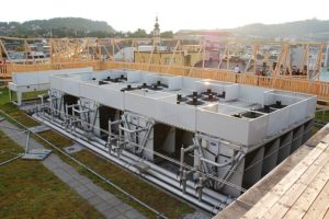
Industrial facilities such as manufacturing plants, labs, processing plants should maintain proper temperature, humidity, air quality and cleanness. Contaminants must be collected and treated before being discharged from the building to the ambient. For the workers efficiency, the environment should be comfortable and healthy, the contaminants like COx should properly treated.
By using HVAC analysis the contaminants at different locations and concentrations can be determined, the results can be used to further improve the design of the HVAC systems.
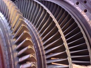
Gas turbines are widely used for aircraft propulsion, land based power generation and industrial application. The blades are responsible for extracting energy from the high temperature, high pressure gas produced by the combustor. Thermal efficiency of the gas turbine is improved by increasing turbine rotor inlet temperature. But high temperature can damage the turbine blades.
So turbine blade cooling is very important process. The cooling process is achieved by either air or liquid.
By using computational fluid dynamics, the cooling process can be analyzed for the turbine blades. Apart from the studying the flow pattern the blade efficiency can be improved many fold based on the CFD analysis.
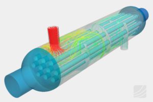
The performance of the heat exchanger is affected by many reasons, but the major reason is formation of dead zones. Dead zone is the area where the flow is minimal, and it decreases the heat transfer between two fluids. This dead zone formation is also one of the reason for foul formation. In heat exchanger with baffles, some serious problems will occur due to the implementation of the cross flow.
By doing the computational fluid dynamic study the detailed understanding of the dead zone formation is possible. And also we can study about the important steps to be taken to increase the performance of the heat exchanger. This saves significant amount of cost and time.

In the HVAC system condensing part is very important. The hot fluid is condensed and the heat is exchanged with the ambient. The performance of the system depends on fluid flow rate and flow pattern. To increase the fluid flow some of the flow parameters need to be optimized. For example, while for a chiller plant the efficiency is directly proportional to the rate of fluid flow. Again the fluid flow is depends on the flow parameters (fan RPM, cowl shape, fan position) in the chiller unit.
By using computational fluid dynamics (CFD), we can study the effect of various design combinations, and the most optimum design can selected based on the results. This reduces the cost and time involved in doing repetitive experiments .

In many industrial fluid systems pressure drop is a commonly occurring phenomenon. Pressure drop occurs when the flow encounters resistance due to surface friction, viscosity and some other parameters. For example consider an basket strainer , where there are many factors affecting the pressure drop. The wall resistance, flow through the perforated sheets, wires and other filtering components highly affects the pressure drop.
By using computational fluid dynamics (CFD) we can study the pressure drop variation across the basket strainer. And also the pressure drop at different locations can be located out. Based on the cfd results and plots we can improve the design of the basket strainer.