CFD applications : MRF approach for turbo-machinery simulation
CFD Applications : MRF Approach for Turbo Machinery Simulation
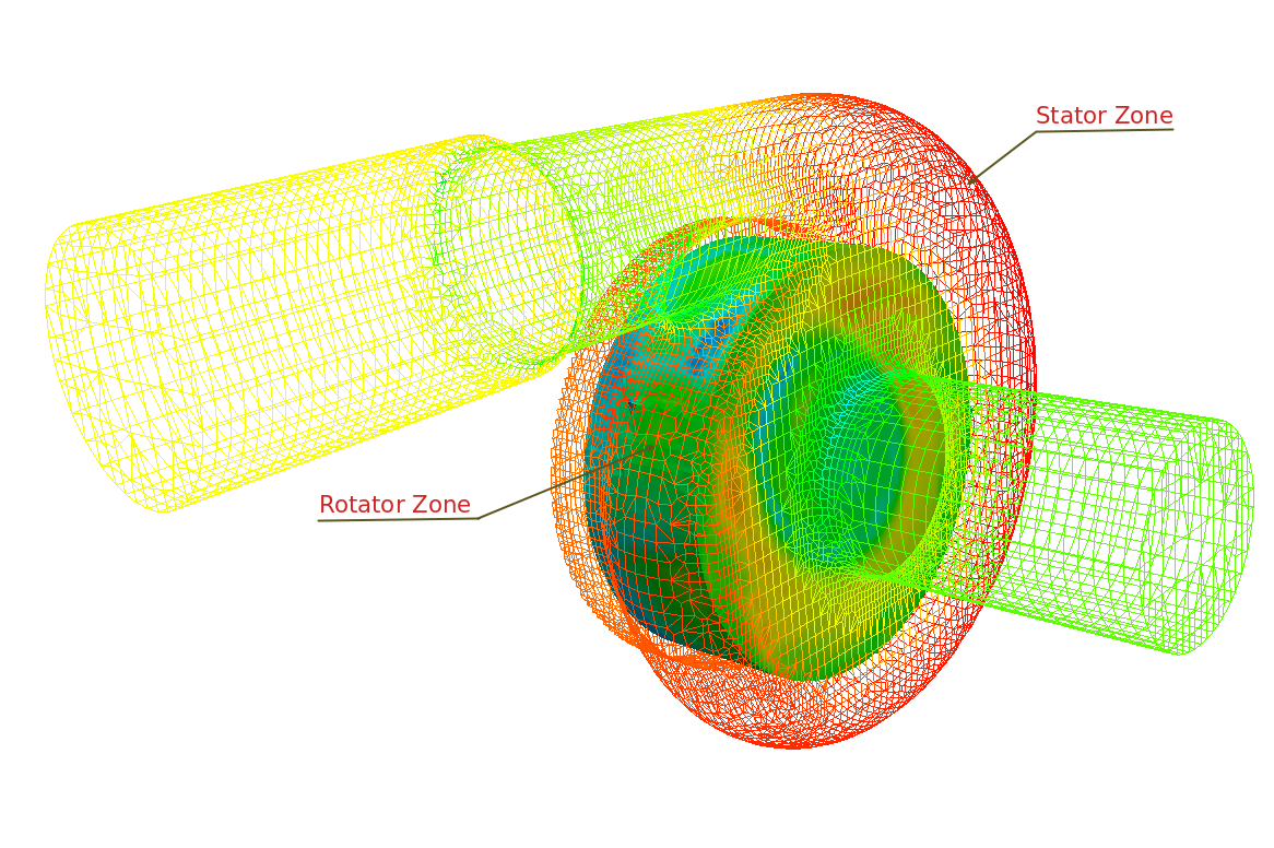
Multiple reference frame (MRF) is used in CFD simulations, where separate static and rotating zones are present. For example, in a centrifugal pump, impeller imparts a rotating motion to fluid. The zone of fluid between casing and impeller is a non rotating zone. In a CFD simulation of centrifugal pump, if rotation motion is given to the region of mesh representing the impeller, solution will be based on an unsteady algorithm. The simulation can be made steady, if frame of references is changed. For instance, with respect to an observer standing on a stationary reference frame impeller rotates. But when the observer is on impeller, rotating impeller will look as stationary. In similar manner, steady RANS could be solved for centrifugal pump on a stationary frame, with a condition for providing additional source terms (inertial forces due to rotating reference frame), whenever rotating fluid zone is being solved.
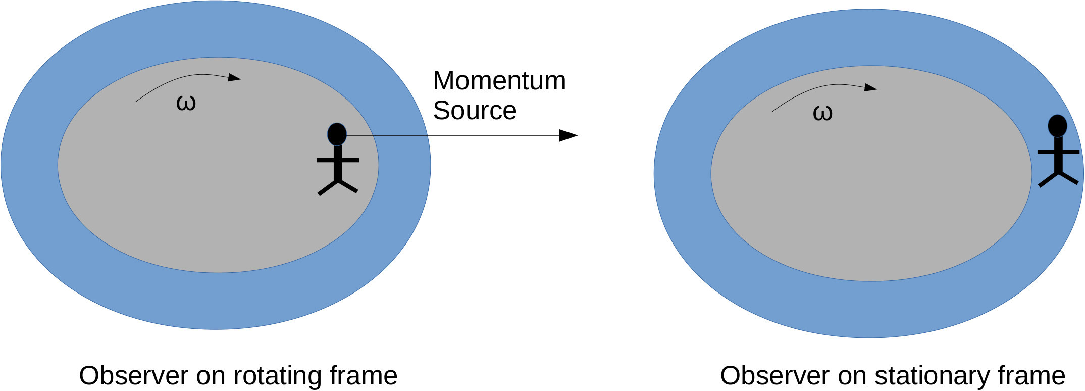
Thus CFD algorithm uses multiple reference frames for making an unsteady case apparently steady. MRF approach is widely used in solving industrial problems. A proper selection of turbulence models and wall y+ in CFD could produce results very close to experimental findings. The MRF is zone specification in a CFD solver includes, specifying an origin point, axis and speed of rotation. Solvers also allow for non-rotating patches in MRF zones. Some other examples of MRF simulations are flow analysis of fan, turbine, mixer, agitator etc. After an MRF simulation a validation can be done with experimental data. Except MRF, dynamic mesh is another technique which can be used to solve similar problems. Courant number should be taken care for dynamic mesh motions. Dynamic meshing is a computationally intensive technique, hence it is always better to use MRF technique as far as possible.


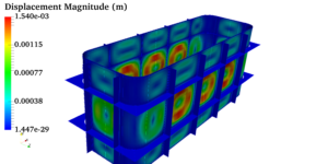 Pressure vessels, pipes, expansion joints etc. are basic equipments for process industries. Pressure vessels are vessels working under internal, external or vacuum pressure, and possibly subjected to high temperature. Proper design and analysis is very important for the pressure vessels, as their failure can cause lot of hazards. Codes/ standards are used in the design phase, followed by analysis to ascertain stresses are within the allowable range. ASME provides wide range of guidelines for the proper design of such vessels.